Bill Griffith, Power Product Manager, Keysight Technologies, Santa Rosa, CA
Electronic loads began as a specialized product for testing DC power supplies; electronic loads reveal a power supply’s reaction to various load conditions. The use of FET switches and non-reactive components, commonplace within electronic loads, avoid resonances and instability. DC electronic loads are growing in popularity as more electronic devices convert and store energy. They are utilized in testing most sources of DC, including batteries, solar panels, LED drivers, DC-DC converters, and fuel cells.
Tip 1: Testing a battery – constant current (cc) mode
The current priority mode is the most popular of testing modes for an electronic load. A basic use for this setting would be to measure the total energy stored in a battery. As the battery supplies current, its voltage drops. By using this characteristic (voltage profile), we can predict a battery’s capacity in terms of time.
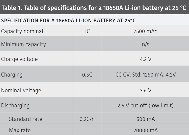
As a constant current test example, we use a Li-ion 18650 battery. The capacity (C) measured in mAh, is used to calculate the current for charging and discharging. When charging, the current is limited to 0.5C (in our example 1250mA) charging needs to stop before the battery voltage reaches 4.2V (Table 1).

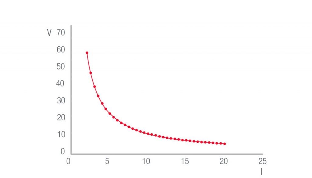
Discharging uses a similar constant current process. A sizeable current drain is inadvisable as this shortens the life of the battery. Also, it’s crucial to stop pulling power at the point where the battery reaches its low voltage limit (2.5V) to prevent further potential damage. The discharge plots in FIGURE 1 exemplify the runtime of the battery.

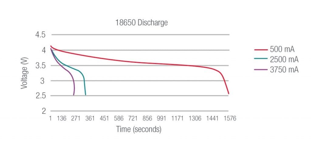
A battery can support discharge at their max rate. However, Li-ion batteries yield a higher capacity if discharged at a fraction of this value. Low temperatures can influence both voltage and capacity.
Many other battery attributes are determined using DC Electronic loads, capacity, internal impedance, charge /discharge long term performance, low-temperature behavior, and abusive extremes. Capacity being the most common, as it yields the battery’s run time. Tests using variable current drain to simulate a device as it comes out of sleep mode into an active state, for instance, can paint a picture of how the battery holds up to various discharge rates (Fig. 1)
Li-ion batteries will have a long life when they operate over a narrow range. Avoiding a high charge voltage (>4.1V) and a low discharge voltage (<2.6V) reduces the stress on the battery. Calculating the battery capacity multiplies the discharge current 500 mA by the run time, 4.5h, or 2250mAh. The measured capacity is slightly lower than specified due to the narrow operating range 2.6 to 4.1V
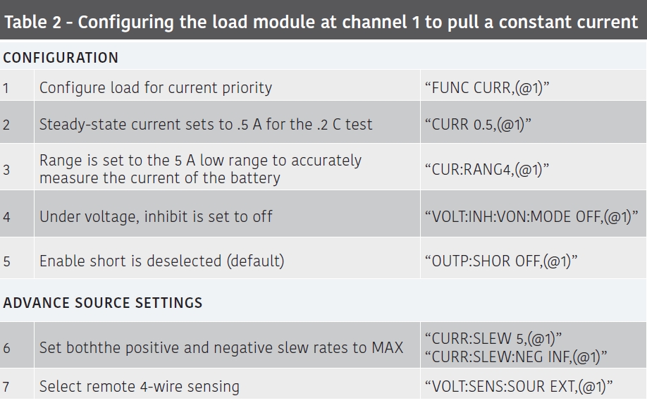
Table 2 shows the standard commands for programmable instruments (SCPI) to configure the load for current priority:

Tip 2: Testing the transient response of a power supply
The majority of power supplies use a voltage regulation circuit to provide a constant voltage. In certain conditions, however, the load may exceed the circuit’s ability to maintain a constant voltage, and as a result, transient voltage spikes can manifest.
To quantify the transient response, set the load so that the power supply is supplying full output voltage with a current that is half the supplies maximum. Then suddenly increase the load to force the power supply to provide maximum current, and then decrease the load to restore the power supply to half capacity.
The time taken for a power supply to recover from a significant change in load is known as its transient response time (FIGURE 2).

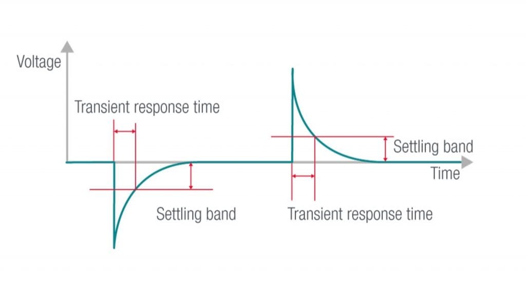
The supply is considered recovered, once stabilized within its settling band. As an example, the Keysight E36312A specifies less than 50us to recover within the 15mV settling band. This follows a load change of 50% to 100% of the maximum output current.
Measuring this response time using load resistors and switches could pose a challenge. Power resistors, often wound components, possess an inductance, which can interact with the transient from the power supply. The use of DC electronic loads avoids this additional interaction.
The DC electronic load can be configured in either resistance or constant current mode to achieve these measurements. In the former, the value of resistance required to generate the desired current (50% or 100%) would need calculation. The latter simply requires the load to be set to the desired current values.
With the load configured, the next step would be to create a waveform (step or pulse) to load the power supply in such a way to generate the transient(s). The Keysight N6700 series have a series of built-in waveforms that facilitate this. Generating a dynamic load is created by describing just a few points. A step waveform generates a single transient as the current value changes from 50% to 100%, a pulse generates two transients, one for each edge (FIGURE 3).

Tip 3: Testing a power supply’s ability to limit current
In the event of a fault condition, power supplies include a current limiting protection circuit. To protect the supply itself and connected equipment. When using an original equipment manufacturer (OEM) Power Supply. It’s important to know that the performance in this regard is right for the intended application.
There are generally 3 types of current limits
- Conventional current limiting
- Power supplies that can transition between constant voltage (CV) to constant current (CC)
- Fold-back current limiting power supplies
The first two are very similar in function, differing only in the degree of regulation in the constant current region (FIGURE 4) this region is adjustable in the case of the supply CV/CC capability.

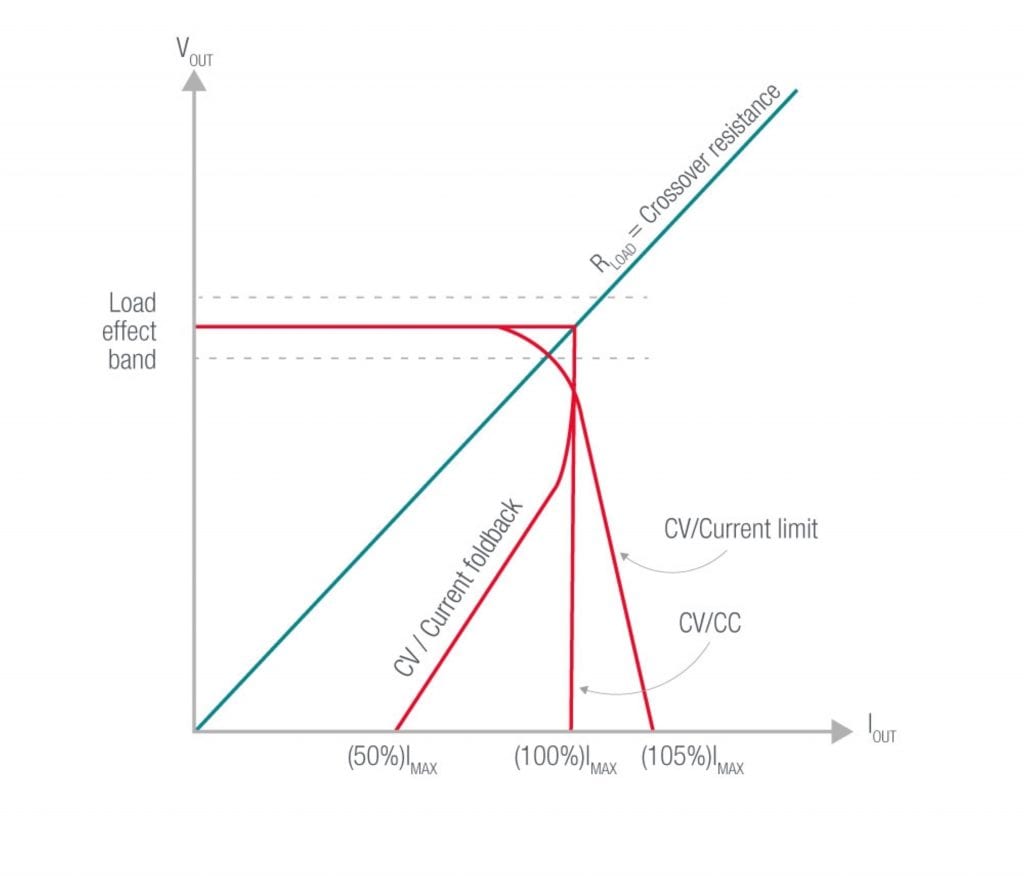
Current limiting capability test
The test begins with the DC electronic load configured to draw a minimal current from the power supply. The load resistance is reduced in steps while monitoring the output voltage and current. The output voltage remains constant as the current increases until reaching the current limit, then the voltage drops.
This drop is known as the crossover region. As the load resistance decreases further, the current limiting circuitry of the power supply is now active. There is a sharp transition to this constant current region with a high-quality supply.
Tip 4: Testing DC-DC converters
DC-DC converters, within their working range, can accept a wide range of input voltages and provide an isolated stable output voltage. Their use in electronics is commonplace. Emergency vehicles can make use of a step-up DC-DC converter to power computers and their peripherals.
Many computers require a DC supply voltage in the range of 14-19V, using a DC-DC converter to power these devices directly from the vehicle’s 12V battery, is much more efficient than using a AC mains inverter to power each of the devices via its AC-DC power supply.
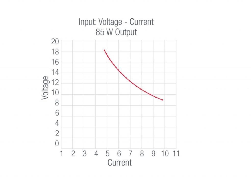
DC-DC converters are efficient, typically better than 96%, and are constant power (CP) devices. With a constant load, they consume constant power by increasing the input current as their supply voltage drops (FIGURE 5).

Protecting the converter
Because of its nature, the converter requires more than a single current limit. A converter needs more current at lower supply voltages and less current at higher voltages. A single limit set to handle the large current necessary at a low voltage will not protect the converter at a higher supply voltage. At a higher voltage, the converter would endure too much power before tripping the current protection. The key is to select a power supply with over power protection (OPP) or output LIST capability.
A second safeguard, overcurrent protection (OCP) can disable the output when an overcurrent condition persists. At the current limit, the supply holds the current constant (CC) but allows the output voltage to fall. Potentially, the voltage can drop below the operating voltage of the converter, letting it go into an unstable state. Overcurrent protection prevents this by shutting off the supplies output.
A third safeguard is an undervoltage inhibit set on the DC electronic load. In a test, the DC electronic load protects the converter by monitoring its’ output voltage and only draws current while it’s sourcing a nominal voltage. An inhibit function, turns the load off until the converter restores its proper output voltage.
Testing the power converter
The N6700 Series modular power system provides a four-slot mainframe that can hold an N6790A dc electronic load along with a power supply module in a single chassis. The power module, programmable for different voltages, can easily simulate the varying voltage of an automobile, while the load, configurable to sink constant power, pulls 85W from the supply. An 85W load represents a laptop and several peripherals connected to the converter.
The efficiency of the converter, calculated at each voltage, is the output power of the converter, divided by the input power. The former produced and measured by the supply, the latter by the load.
Results
Initially, 18V is applied to the converter while it powers an 85W load. The test continues by lowing the voltage in 500mV steps, measuring the input voltage and current at each level. This process continues until the input voltage reaches the lower limit of the converter; in this instance, 9V (FIGURE 6). The load is removed from the converter at this point by the under-voltage inhibit circuit, making it easier for the converter to recover once a valid input voltage is re-applied. The results show efficiencies in the range of 97-98%.

About the author
Bill Griffith is currently a Power Product Manager with Keysight Technologies. He has over 25 years working in the power and energy applications with Keysight (formerly Agilent Technologies and Hewlett-Packard). Bill graduated from Colorado State University with a BSEE.