
Dr. ASHWINI SINHA, Associate Director R&D, Linde Electronics
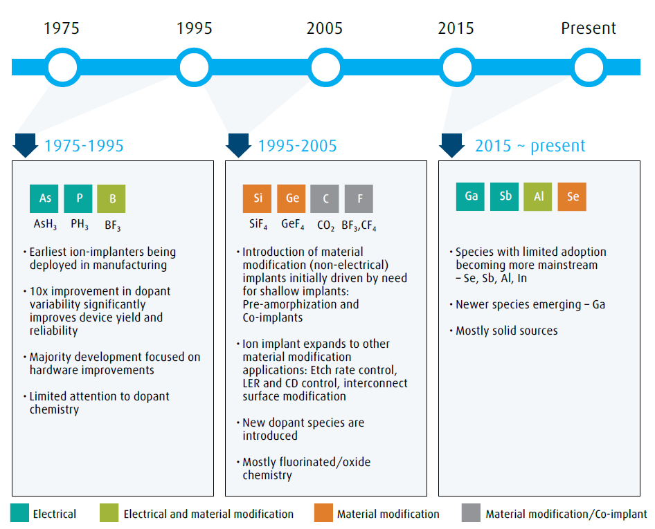
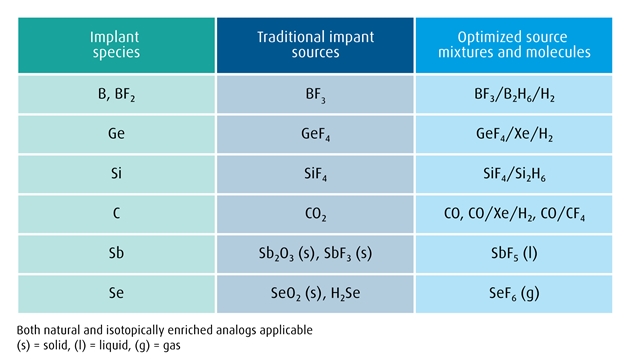
Ion implant is one of the key processes that have made IC devices economically viable and eventually ubiquitous in our lives. During the early years of IC fabrication up until the mid-1970’s, thermal diffusion was the primary process employed for introducing n-type or p-type dopants into the silicon substrate. The dopant dose variability across single wafers and from wafer-to-wafer was in the range of 20%-30%. Such process variabilities limited the manufacturing process yield and reliability and were a barrier to the economy of scale and to unit cost reductions. The ion-implant process offered a solution by its ability to place desired atoms in a substrate with a very precise location, dose and depth control. Today, the ion-implant process is used to implant over 15 different atomic species for a variety of applications. Figure 1 illustrates the evolution of implant species as they entered high volume manufacturing.

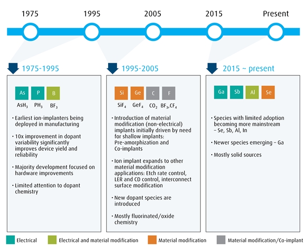
Smaller and more complex transistors have required thinner films with shallow implant depths, higher dosing, and non-electrical material modifications. However, the new implant species and tighter process windows in turn have revealed challenges with tool operation that impact final device performance and process line productivity.
Below, we describe how the chemistry inside the tool must be addressed in order to continue to achieve commercially viable implant processes. We highlight one of these key chemical challenges, and our approach to rapidly screen and optimize new source materials to overcome it through two case studies.
Halogen Cycle: A tool productivity killer
Although fluorinated gases are preferred for implant material dopant sources due to their favorable ionization behaviors and volatility, the fluorinated products generated in the arc chamber plasma strongly react with the components of arc chamber primarily made of tungsten or molybdenum. Figure 2 presents the mechanism behind the halogen cycle on arc chambers for GeF4, which is indicative of the halogen cycle for all the fluorinated source materials.

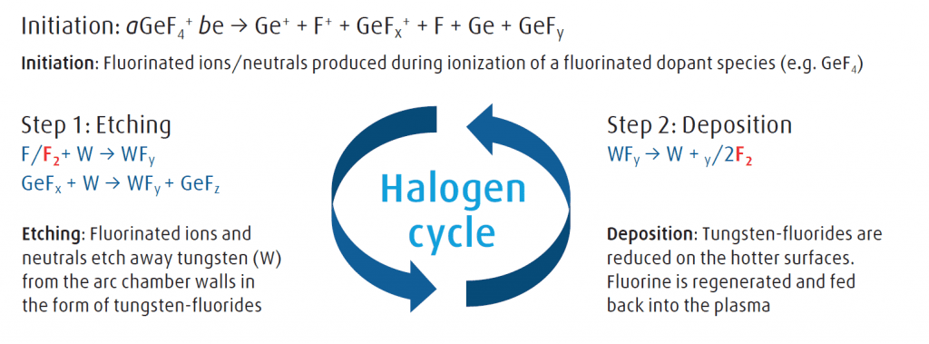
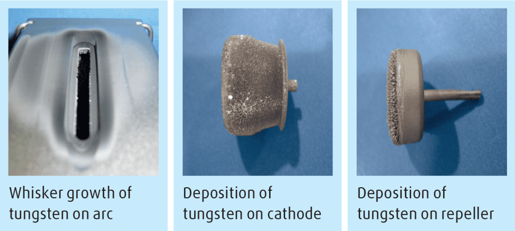
The sequence of etching and deposition keeps regenerating the consumed fluorine, resulting in a self-perpetuating process known as the halogen cycle. This phenomenon leads to whisker-like growth of tungsten on arc chamber components like the cathode, repeller and aperture (Figure 3), and on other components of the ion source like the extraction electrodes and isolation components. Oxide species present very similar sets of issues due to formation of tungsten oxide in the arc chamber. Eventually this leads to the failure of ion-source. Tool operation is halted, and the ion-source has to be rebuilt before resuming the operation. This halogen cycle is the cause of the most common failure modes experienced during operation of implant tool, which we list below.

- Beam glitches – Deposition on cathode, repeller and electrodes
- On-wafer Defects – Undesirable W growth in ion-source / beamline, compounded by beam glitches
- Beam non-uniformity – Deposition on aperture
- Electrical shorts – Deposition on isolation bushing
With the halogen cycle unmitigated for a dedicated GeF4 operation, the mean time between failures for an ion source can be as low as 50 hours. Previously, applications were equally weighted towards fluorinated (BF3) and hydrides (AsH3 and PH3) as the dopant source materials. Implant engineers were able to alternate between hydride and fluorinated species, and the hydrides acted as cleaning agents to reverse the adverse effects of the halogen cycle. However now the application mix is heavily weighted towards fluoride and oxide processes, and this solution is no longer possible. The introduction of these second-generation implant source materials emerged as a tool productivity killer with the halogen cycle as the leading cause. The engineers were finding it difficult to deploy these new applications without addressing this serious issue.
The solution: Role of implant source chemistry
During the first generation of tools and processes, ion implant development was driven primarily by physics: ionization; ion selection; and strength, energy and shape of the ion beam. With the second generation of processes and source materials, the chemistry inside the tool became an issue, as demonstrated above by the problems with the halogen cycle. In this section, we describe our approach to develop optimized dopant source materials which addresses both the physics and chemistry requirements of newer ion implant processes to continue to enable high tool productivity and device performance.
It is important to note that because deposits form continuously during the halogen cycle, it is far from optimal to implement a post implant clean solution to remove the previously formed deposits. Not only does such a cleaning option result in unacceptable variability between cleaning cycles, but also adds to the equipment downtime while post implant cleaning is being performed. One needs to identify in situ measures to abate the active fluorine ions/neutrals generated during initiation and disrupt the halogen cycle. This can be achieved by co-mixing a suitable chemistry with the fluorinated implant source materials.
While addressing the chemical problem, one must also retain the physics performance of the tool, as indicated by the key metric of beam current. Hence, the overall challenge is to solve and optimize both sets of variables: identifying a gas mix chemistry which extends tool uptime and reduces variability while maintaining high beam current.
Appreciating the challenge, Linde designed and built an ion-implant test stand to develop novel gas chemistry solutions to enable high productivity for the implant process. With the deep understanding of both implant process physics and gas-phase chemistry, we invented novel dopant source solutions that not only mitigate the halogen cycle or oxygen attack but also increase the beam current to further improve the implant tool throughput. The test system is designed to rapidly screen and optimize different gas chemistries, and thus significantly reduce the cycle time for implant process owners to deploy the best-in-class solutions. Figure 4 lists several new dopant sources currently offered by Linde that are driving implant tool productivity by delivering high marks on all the key metrics listed in the section above. The two case studies presented below showcase the benefits implant process owners derive by implementing these novel solutions.

Case Study 1: Novel dopant source mixture for high dose low energy boron implant
Boron is the most widely implanted species in an IC device, and is usually doped in the form of B+ and BF2+ ions. However, the dosing and implant energy required varies widely among the application device types and specific process applications (Figure 5).

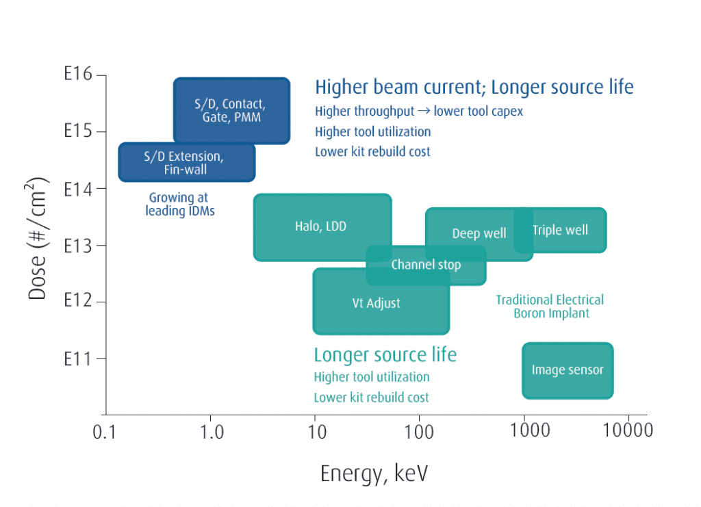
Continuously shrinking device dimensions and the advent of FinFET architectures pushed certain boron recipes into the very high dose (E15 – E16 atom/cm2) and low energy (sub 1 keV) implant regime. These high-dose low-energy implants are much more challenging than other boron recipes First, the implant tools are usually beam current limited at these low energies, significantly reducing the wafer throughput. While the average throughput for other recipes are in the range of 50-100 wph, the throughput for these recipes can be limited to 15-30 wph . Secondly, these low energy implant layers are usually very sensitive to beam glitches and leading to on-wafer defects. It is not uncommon that the ion-source failure may happen due to inability of the implant tool to achieve beam spec requirements for one of these high dose low energy recipes. There was a clear need to develop solutions to improve beam current (equipment throughput) and ion-source lifetimes for tools running these recipes.
Linde has developed a novel mixture of B2H6, H2 and BF3 (Boron Trimix) which is widely being adopted by IDMs to improve the productivity of their boron implant. Linde also utilized the advantage of its UpTime ® based sub-atmospheric delivery system to package the mixture in a single container and avoid the need for a separate gas manifold to deliver this mixture to the ion-source chamber.
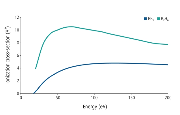
Development of this solution required a deep understanding of the ionization process and resulting chemistry. All other potential candidates, despite offering the possibility of reduced fluorine attack, resulted in undesirably lower beam current (Figure 6). We utilized the favorable ionization properties of B2H6 to fundamentally change the plasma chemistry and physics inside the arc chamber. Under this modified plasma environment, the ionization of BF3 is enhanced to produce more BF2+ and B+ ions due to such properties as ionization cross-section highlighted in Figure 7.

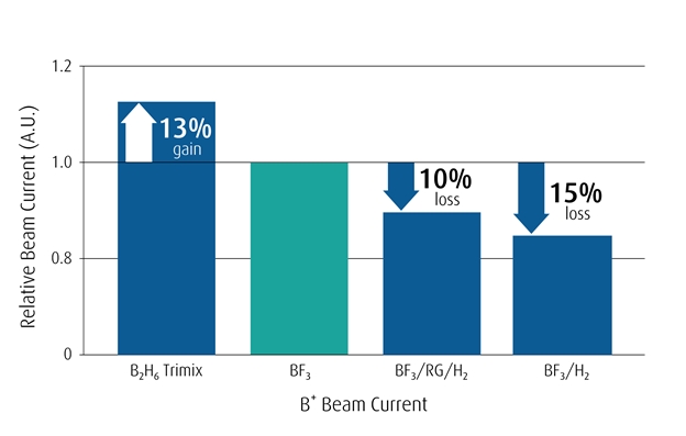

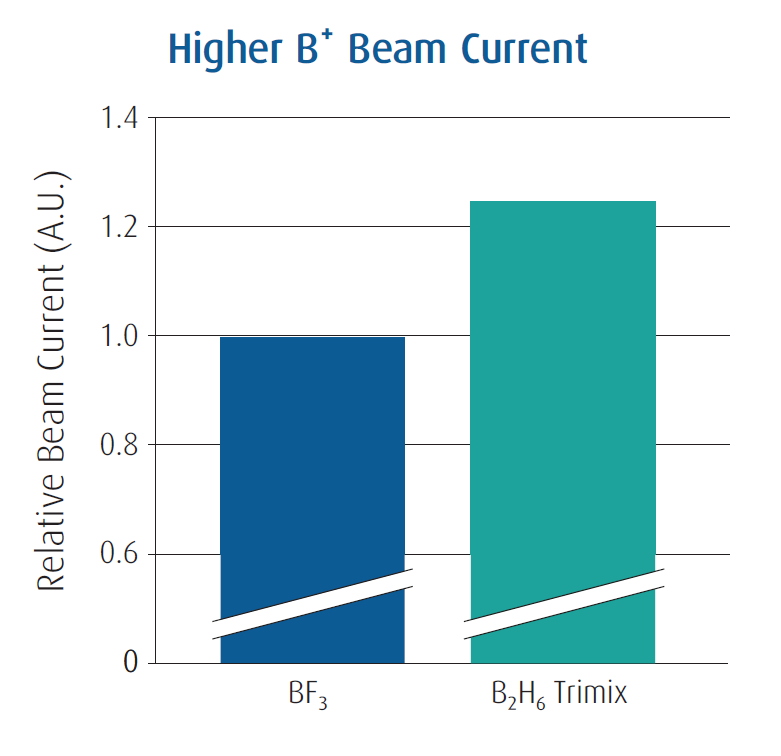
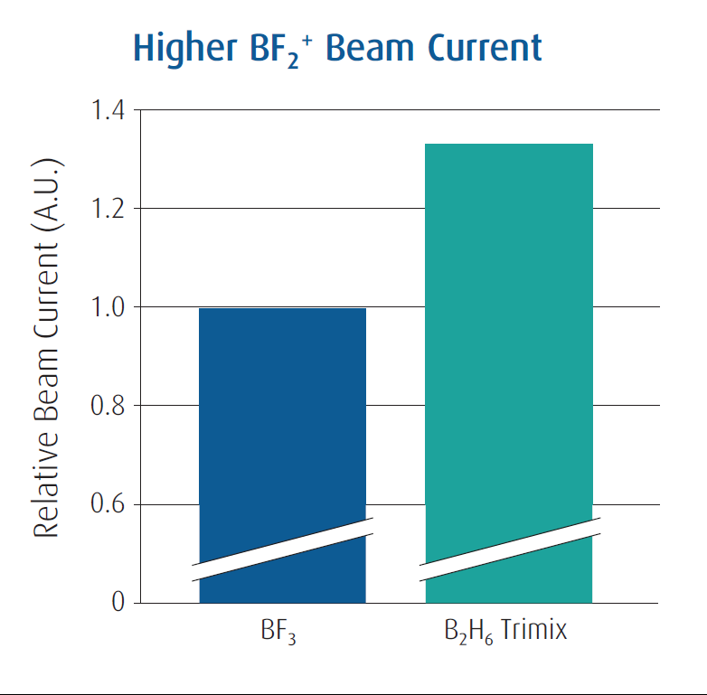
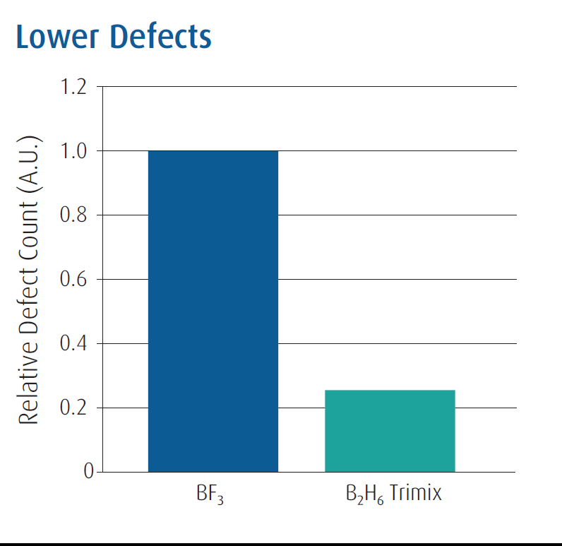
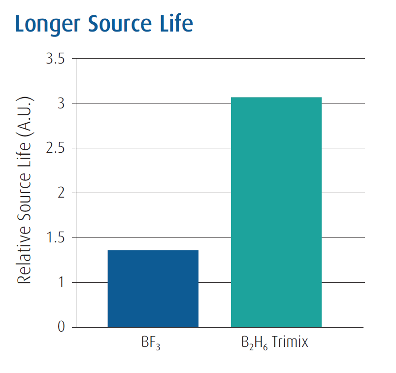
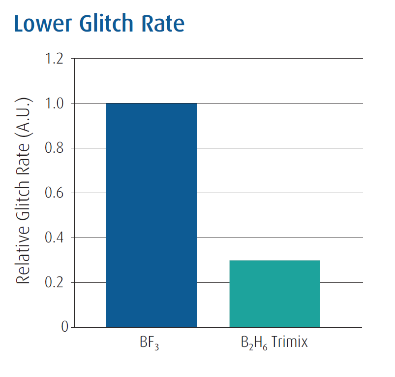
The in-house test demonstrated that boron-trimix delivered at least 13% improvement in beam current for B+ over conventional BF3 dopant source. Hydrogen and hydrides generated from H2 and B2H6 mitigated the halogen cycle and a very clean operation was observed during marathon tests. Use of our test stand gave customers a ready-to-deploy best-in-class boron dopant source without the need to spend significant internal development cost and time. Figure 8 shows the summary of benefits that customers have been able to realize by use of boron trimix in their fabs. When the boron trimix was deployed on production tools, 15% – 30% improvement in beam current was achieved
Case Study 2: Gas-like dopant source for antimony
Recently, a third generation of implant species are either becoming mainstream or are candidates for next-generation process flows. Selenium is being explored to reduce contact resistance while aluminum and antimony are finding more use with the growth in the power devices segment. Gallium is emerging as a potential p-type dopant. Coincidentally, the traditional sources for all these new entrants are solids, which present their own set of handling challenges for the development of other implant recipes.
In addition to arsenic and phosphorus, antimony (Sb) is another candidate for n-type doping. However, its adoption has been limited due to non-availability of a gas-based source. Traditionally, only solid sources like SbF3, Sb2O3 or metallic Sb have been used as dopant source. Solid sources are usually delivered via a vaporizer assembly where solid dopant sources are placed in a crucible very close to the arc chamber. The crucible is heated to an elevated temperature (250°C – 1000°C) to volatilize the solids kept in the crucible and then transported via a carrier gas flowing over the hot crucible.
Such a delivery approach suffers from several limitations which are nearly absent for a gas-based source
- Long recipe / beam transition times – 20-30 mins required for heat-up/cool down of vaporizers for every transition
- Limited crucible lifetime – ~60-100 hrs
- Limited flow control – challenging dose control
- Redeposition of solids on colder surfaces – Defects and frequent preventive maintenance requirements
Taken together, these limitations have prevented a wider adoption of Sb doping processes despite superior device properties like shallower implant profile and reduced auto-migration in comparison to As.
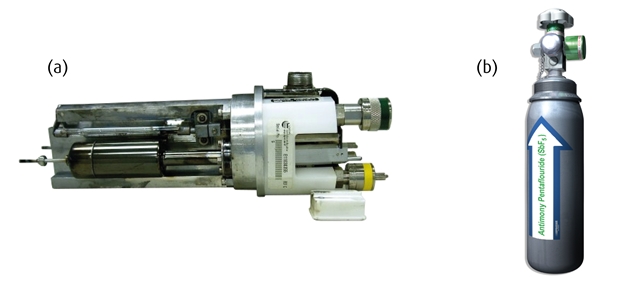
Linde recently introduced a gas-based source for Sb in the form of antimony pentafluoride (SbF5) which replaces a very cumbersome vaporizer operation by a very simple cylinder-based delivery system as presented in Figure 9. SbF5 has several favorable properties that makes it a suitable candidate for a successful dopant source for Sb:

- 7-10 torr vapor pressure at ambient conditions – can be easily dispensed as a vapor via the standard ion-implant gas stick
- Flow control via mass-flow controllers – instant flow change response
- Favorable ionization behavior – high Sb+ and Sb++ generation
- Compatible with standard gas manifold components
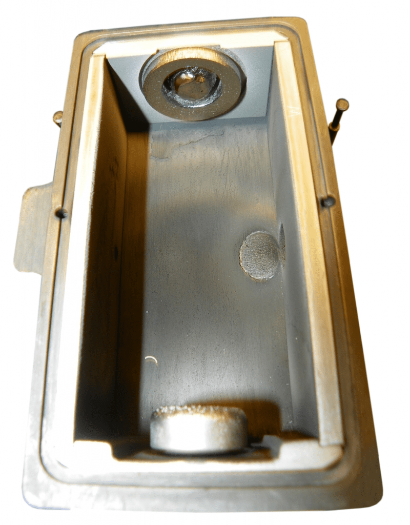
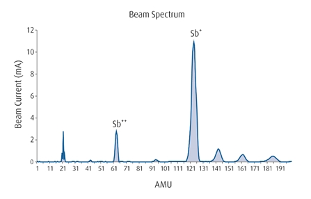
H2, or a mixture of H2 with rare gases like Ar, Kr or Xe, dispensed along with the Sb5 vapor, serves as a robust mitigant for the halogen cycle as is evident from the picture of arc chamber post 200+ hours of SbF5 operation (Figure 10). As noted before, retaining the physics performance of the beam current is equally important to the chemistry improvements. Figure 11 demonstrates excellent conversion to the desired Sb+ and Sb++ ions. Full product qualification is currently underway at several leading OEMs and device manufacturers.


Conclusion
As technology roadmaps evolve and more varied and complex thin films are required, ion implant will undoubtedly continue to be employed extensively to implant new dopant species and to create entirely new materials with implant modifications. To support these new applications, new material sources will also be required. And as we have seen above, both physics and chemistry must be co-optimized to ensure final commercial success.
Linde has pioneered development of novel dopant sources that have enabled implant process owners to increase their equipment throughput, reduce equipment failures and improve process yields. By using our proprietary screening test stand and protocols, we have rapidly prototyped new materials for our customers. These novel dopant materials, in combination with UpTime innovative packaging, offer the best suite of products and lowest cost-of-ownership solutions for ion-implant processes.
Editor’s Note: This article was originally published in the November/December 2019 issue of Semiconductor Digest.